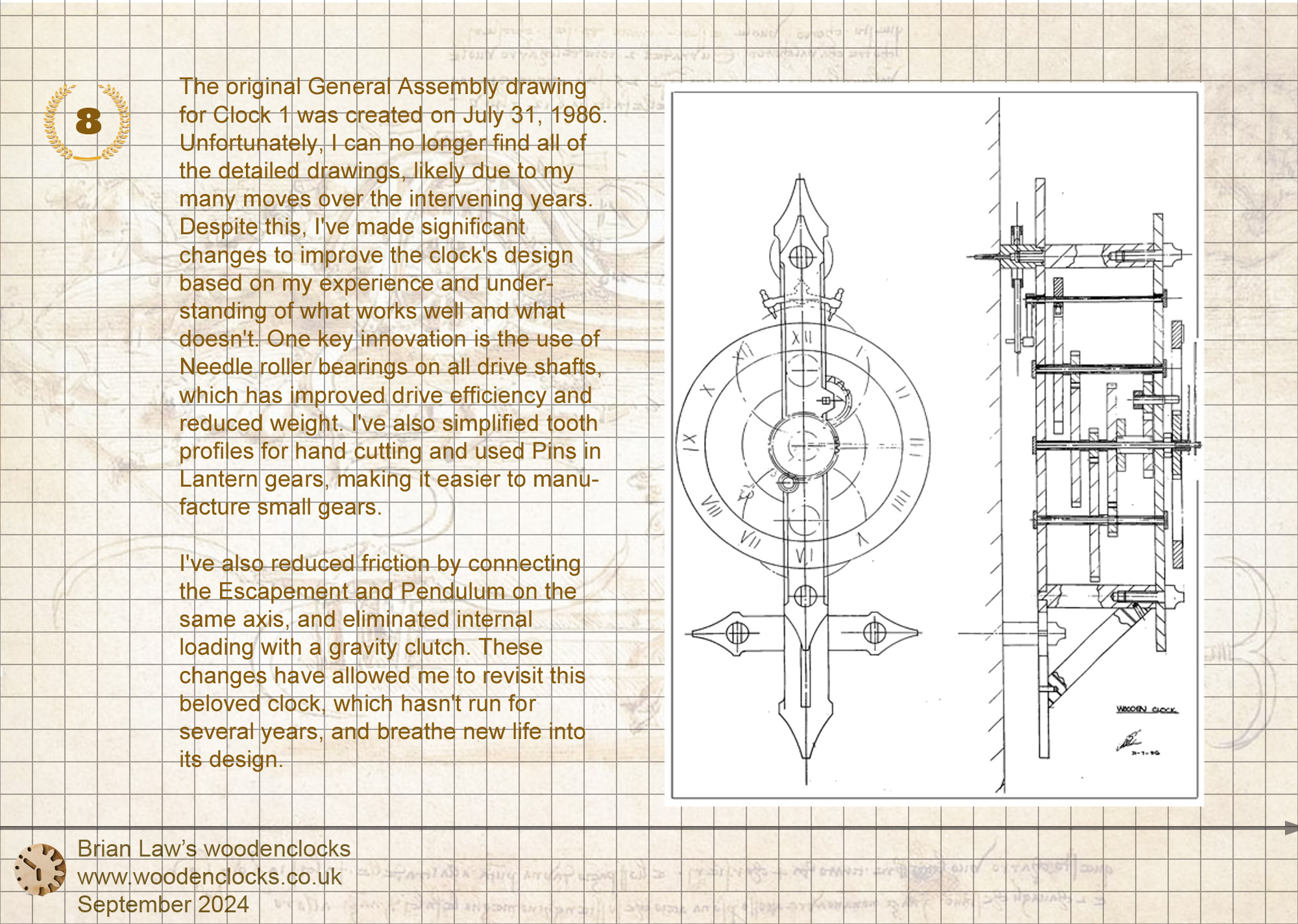
The inspiration for this clock originated from a review of designs I created nearly 40 years ago when Clock 1 was developed as a project to promote a new Bandsaw at the company I was employed by at the time. The success of the Bandsaw sparked a lifelong interest in wooden clock design for me.
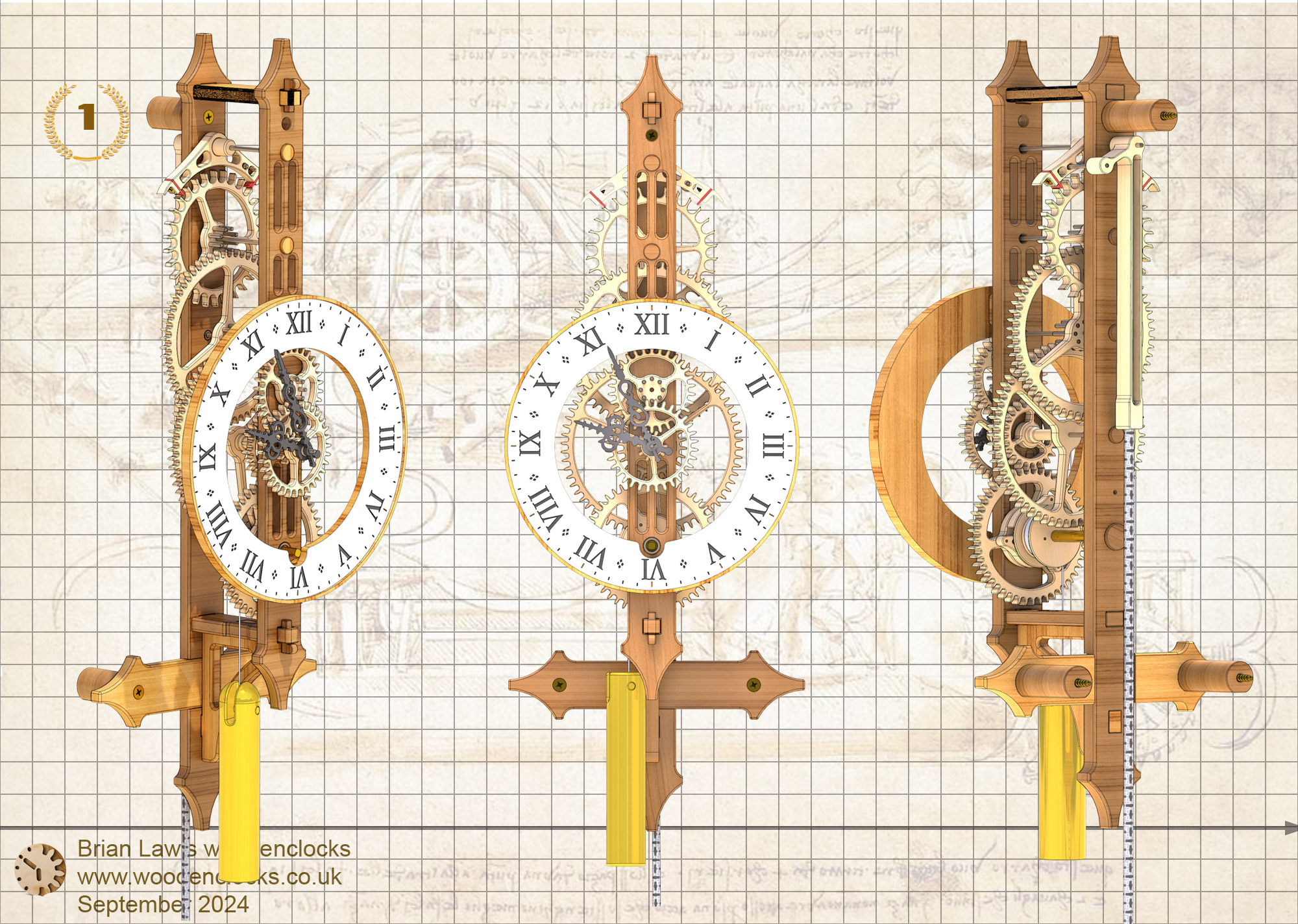
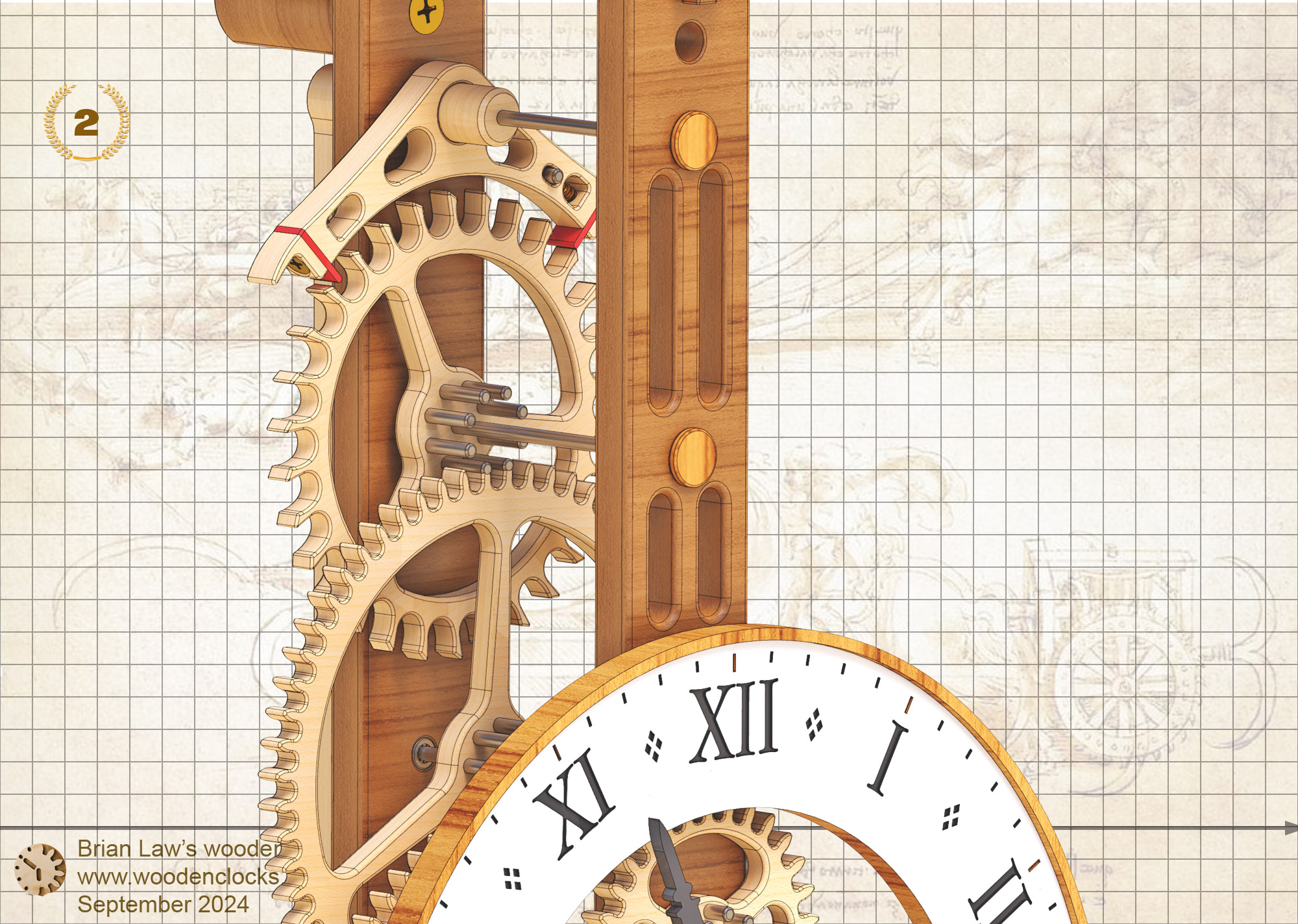
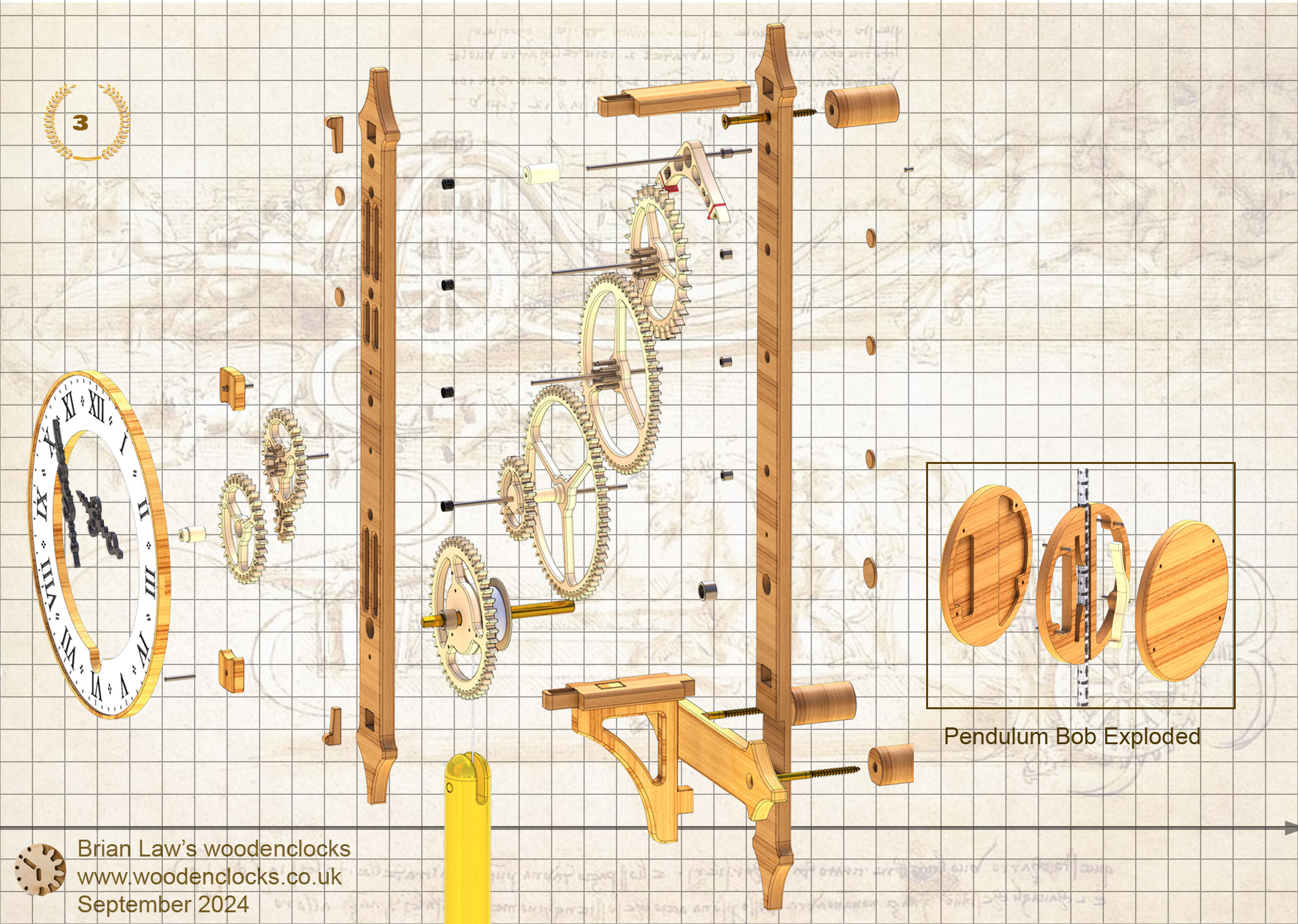
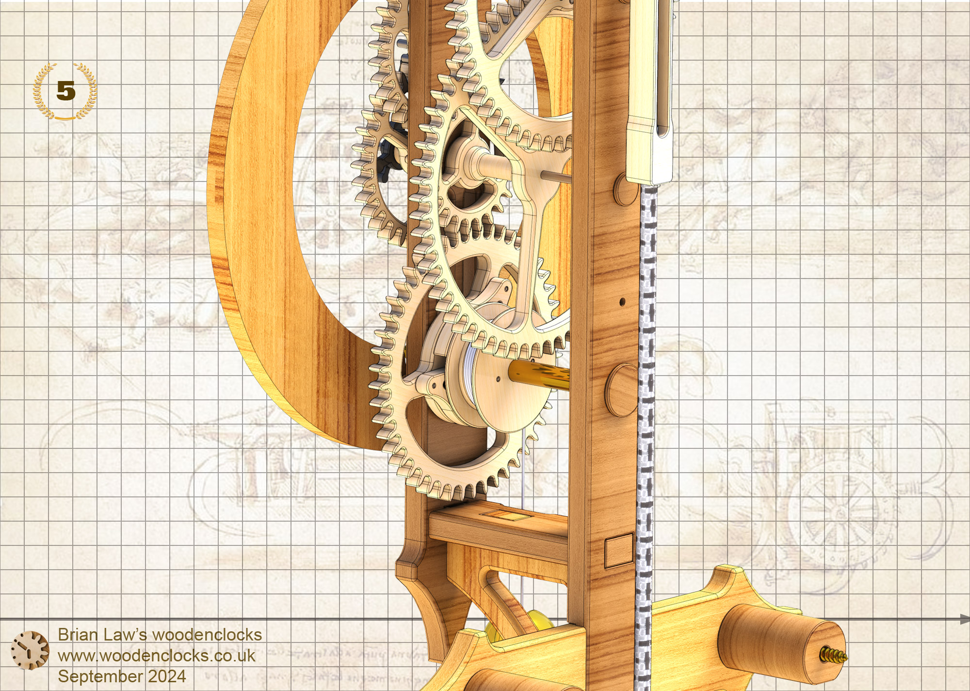
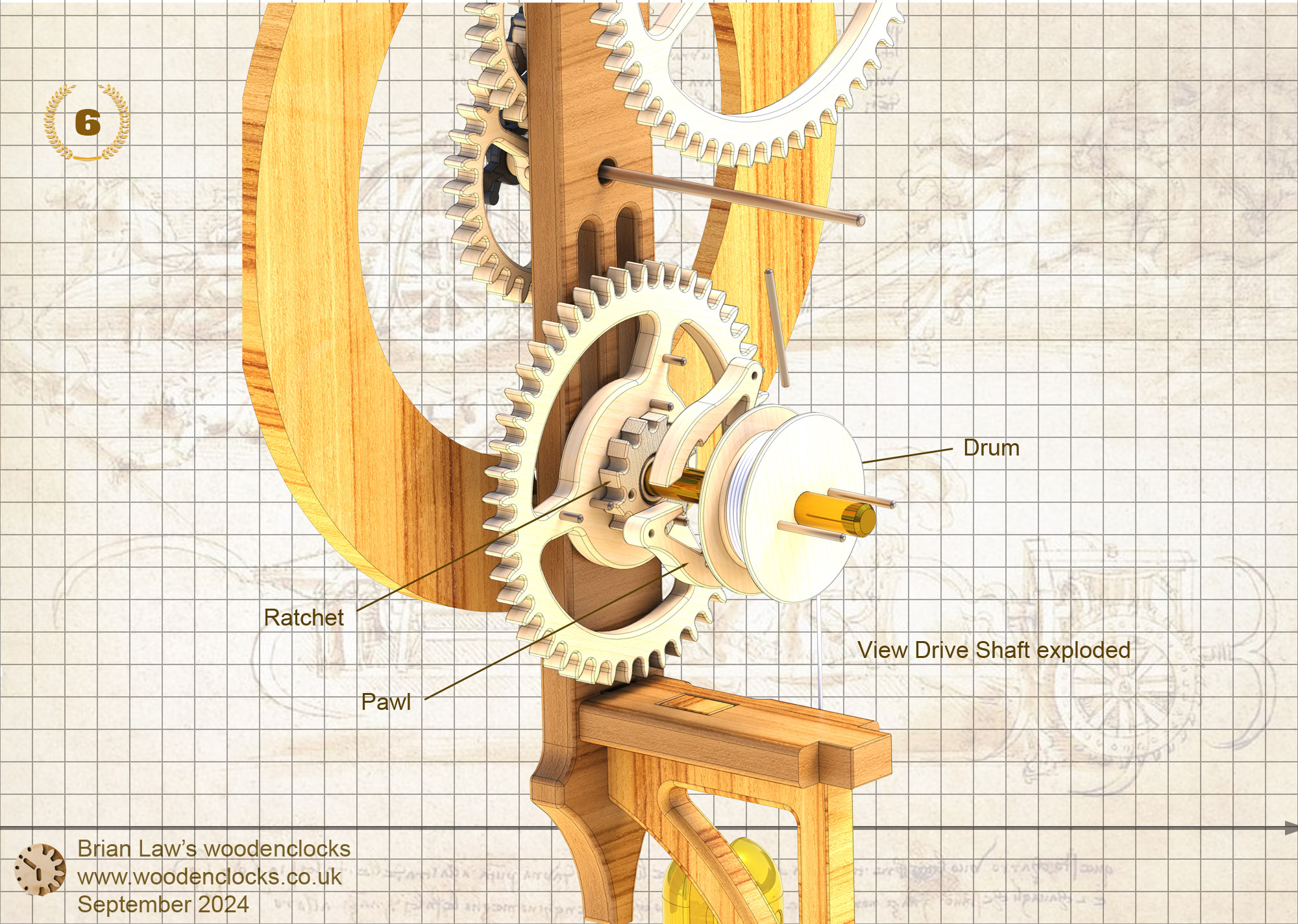
Recently, I stumbled upon the original General Assembly drawing for this clock, prompting me to reflect on the advancements that could enhance the original design if I were to revisit it today. Thus, I embarked on creating this new clock design, incorporating Needle roller bearings on all drive shafts to enhance drive efficiency and reduce driving weight. I also utilized Lantern gears to facilitate the manufacturing of small gears. Additionally, I minimized friction by aligning the Escapement and Pendulum on the same axis and eliminated internal loading with a gravity clutch.
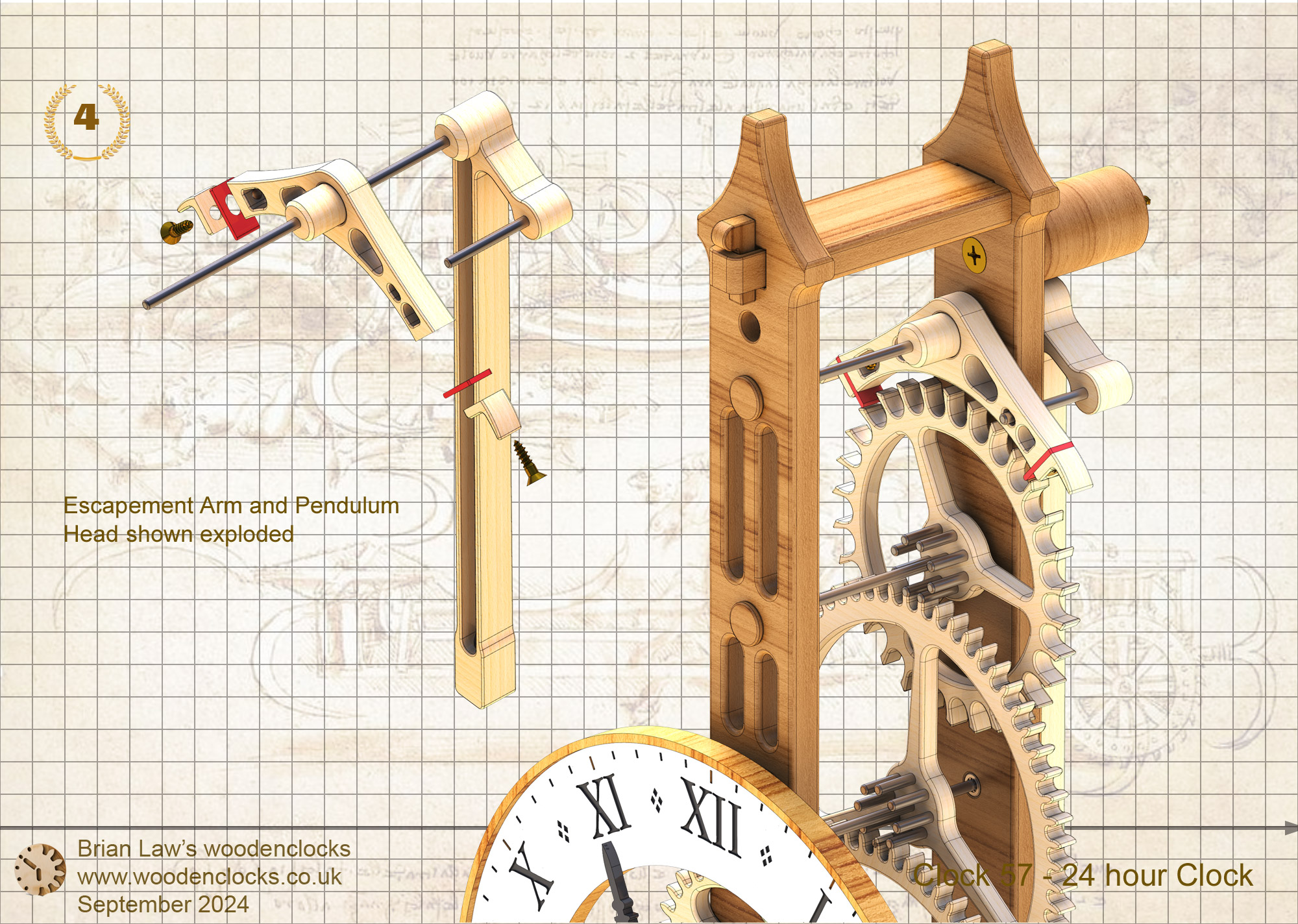
The geometry of the Escapement Arm has been significantly refined to make it more efficient and brought it closer to the original George Graham design.
This new clock has evolved from those revisions and I am pleased to report that it ran smoothly upon initial assembly and continues to function flawlessly several months later. The process of building this clock was truly enjoyable, and I trust that you will find it equally captivating.
DXF files, and the STL and STP files that can be used with your CNC machine can be downloaded here for $26. You also get the unrestricted version of the PDF files that can be printed at full size.
Drawings for this clock in PDF format can be downloaded here. These free files are low resolution and not to scale and only a sample of the full set that comes in the paid for version. Clicking here will download the PDF file directly to your browser, may take a few moments so please be patient.
To print only a single item of the drawing to scale using Adobe Acrobat Reader, do the following:
Go to Edit, then click on Take a snapshot, move the cursor to the top left of the item you want to print and hold down the left mouse button whilst you drag a box around the item. The inside of the box turns blue and you can now go to File and then click on Print. This brings up the print dialogue, make sure Selected graphic is selected and that the Page scaling is set to None and the click on OK. As long as your printer is connected you will have printed the item at size. Do this for each item you want to cut out.
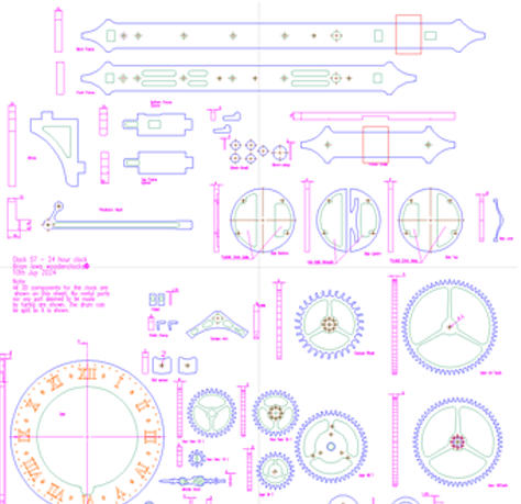
A sample from the DXF file – the file is purposely low resolution, with no vector data. The actual files purchased above are included on one large sheet so that they may be directly loaded into your CAM program.